Modification recommended for Remote Start Gate Device Model GLB
It is easy for a person to start a race by pulling the lever on the BestTrack start gate.
But, for a small solenoid,
it is not such an easy job. You have to give it some help. The notch in the
lever is unnecessarily deep, and it is punched out roughly. There are sharp
edges that bite into
the peg bar. The solenoid must overcome the spring, which is unnecessarily powerful.
|
Step 1 
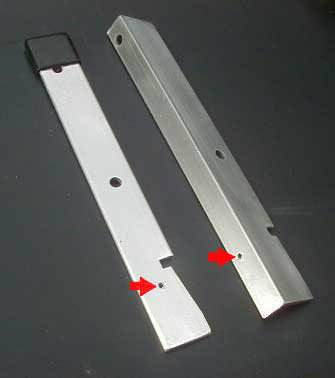
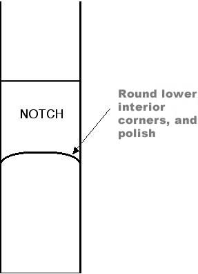
Remove aluminum in the area below the notch, so that the effective notch depth is approximately 3/16". You can use a rough file, but it is much faster to use a belt sander or table disc sander to make the rough cut. Taper your cut to a point 1/2" above the bottom end of the lever. Finish up with a fine file for a smooth finish. |
![]() |
![]() |
|
Step 2 This photo shows the current style start gate lever on the left. and the older, discontinued style lever on the right. In either case, drill a 3/32" diameter hole through the lever, locating it 1 and 1/4 inches from the bottom end. This hole is for attachment of the brass activator rod. Deburr the hole. If you have the new lever, locate the hole on the centerline of the lever. If you have the old lever, locate the hole on the small side of the angle, slightly closer to the outside edge as shown. Let us know what style lever you have. It makes a difference in how we form the brass actuator rod. |
![]() |
|
Step 3 Looking directly into the notch, round the bottom edges so that it engages the peg bar only in the center. You can actually carve the aluminum with an X-acto knife. Make this surface as smooth as you can. If done correctly, the lever's notch will leave no scratches on the peg bar, and the action will be very easy. If there are already scatches on your gate's peg bar, remove them with successively fine grades of sandpaper, and then steel wool for final polish. A smooth surface results in minimum friction.
|
![]() |
|
Step 4 The spring must be modified to exert the minimum force necessary for the action to click into place. Use a needle nosed pliers to re-form the spring ends so that the spring is expanded only about 1/4" when the gate is closed. Before assembly, polish the lever and bracket with steel wool, and apply a little oil on the mating surfaces. Tighten the bolt and nylon-filled nut up to where the parts just start to bind when rotated. Then back off carefully until there is no friction. Too loose is just as bad as too tight. |
![]() |
|
Step 5 Mount your BTG-1 on the track as shown. You may have to temporarily remove your gate to slide the mounting bolts down the channels of the outside lane. Carefully adjust the position of the BTG-1 so that the solenoid opens the gate just when the plunger is pulled all the way in.
|
![]() |
Final Assembly after mounting the BTG-1 to your track
|
When re-mounting the gate assembly, add a washer and nut to the hinge mounting bolt as shown in the left photo. This acts as a stop to reduce the rotation of the pegs, and limit the travel of the solenoid, assuring proper operation. The pegs still disappear completely into the track, as shown in photo at right. |
![]() |
![]() |